How does a fire design work?
Introductory words
Below I would like to present the so-called fire design. This is the proof of a member or supporting structure exposed to fire. Proof can be provided with simplified methods, although I usually use special finite element programs for use in the event of a fire to verify the components even more economically.
1st step: Choice of the building material as well as the structural fire protection
How long a member or structure can withstand a fire (see step 2) depends heavily on its material properties as well as on its static system. This is because heated members lose their strength and stiffness. This results in the following relationships, which strongly determine the heating and thus the load-bearing capacity of a member:
- How quickly does the material heat up? Various material parameters are important for this, such as thermal conductivity. Members out structural steel heat up much faster than members, for example out of concrete. The properties of the most important building materials (steel, concrete and wood) at high temperatures are specified in the relevant standards, the so-called Eurocodes.
- Is the member protected by additional fire protection measures, e.g. by spray, gypsum boards or an intumescent coating? These structural fire protection measures can greatly delay the heating of the member.
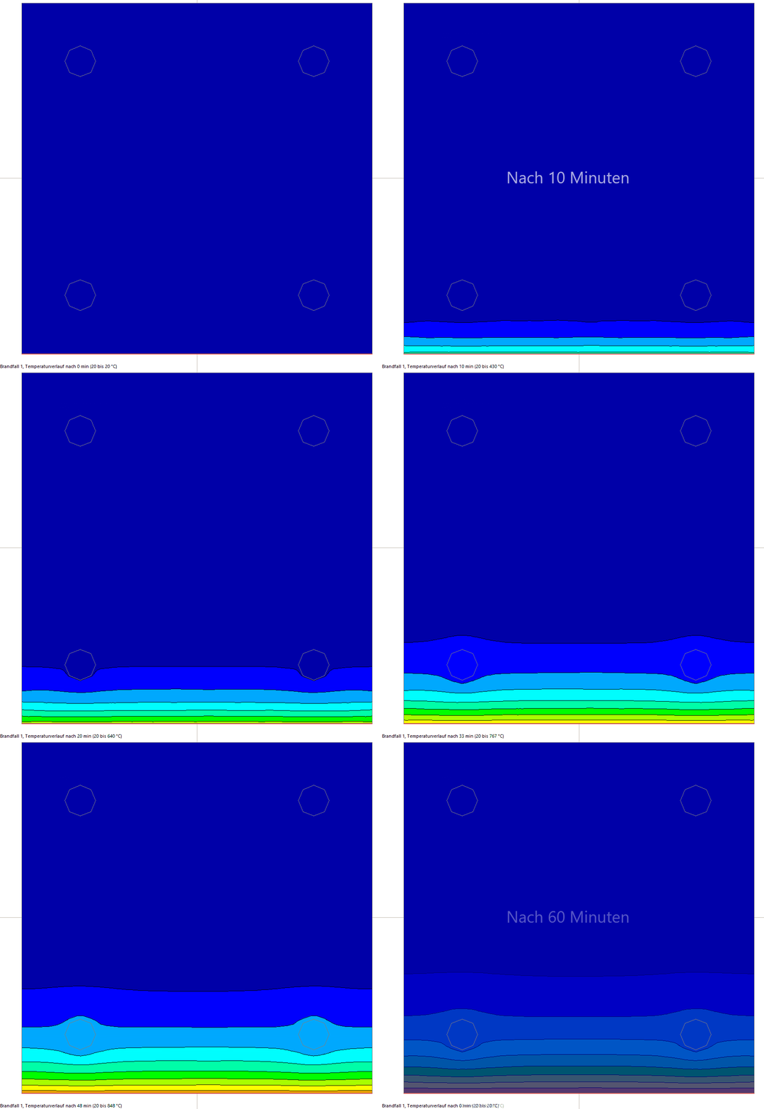
In the animation below you can see an example of how a reinforced concrete column exposed to fire on one side heats up over time. Further down on this page you will find information on the selected fire exposure, the so-called ISO standard fire.

Step 2: Requirements for the member and choice of the fire curve
In addition to the material, the fire temperature naturally has a major influence on the heating and thus the load-bearing capacity of the member exposed to fire. At this point, you have two fundamentally different ways of considering a fire in a heat analysis.
The simpler and therefore often used way is to choose a suitable fire curve. With these curves, the fire temperature is calculated using simple mathematical equations as a function of the time/duration of the fire. You can find the most important fire curves at the top of ours Infotheque under the section "Fires". The curves are defined in EN 1991-1-2, which deals with the effects of fire on structures. The fire curves are based on fire tests and are independent of the actual fire loads.
You can also take another route. If you can determine the actual fire loads in your project, it is possible to simulate the expected fire temperatures. In contrast to the fire curves, there are fire courses that correspond to a natural fire, i.e. the temperatures decline after a certain fire duration. The temperature curves that result from the mathematical simulation are therefore also called natural fires. As a mind game, we assume that your project is a larger industrial hall with approximately 2000 m² in which mainly metals are processed. Otherwise there are hardly any fire loads. Since the metals non-combustible, it can be worthwhile to consider natural fires. The fire temperatures will be significantly lower than in the fire curves listed above. This can save the building owner a lot of money, as there is no need for expensive fire protection measures (e.g. intumescent coating) . At least that's the experience from our previous projects.
Which way is the right one now? Fire curves or natural fires? There is no general answer to this. However, for larger buildings and low fire loads the concept of natural fires becomes increasingly attractive. It should not be concealed, however, that this procedure must be coordinated with both the building supervisory authority. In addition, in the case of natural fires, care must be taken to ensure that the agreed fire loads are not exceeded in the future, as otherwise significantly higher temperatures could arise in the event of a fire.
The choice of the fire zone curve naturally has a great influence on the load-bearing capacity of a fire-exposed member or structure (see step 4). The higher the temperatures as a result of a fire and the longer the fire lasts, the more a member heats up. Which fire curve you are allowed to use depends heavily on your project. We often have to do with the following constellations:
- It is a member for a "normal" building, e.g. an administration building. Then the respective state building regulations must be observed, which define the required fire resistance period of a member. These refer to an artificial fire curve, the so-called ISO standard fire. Depending on the duration of the fire, this curve can reach very high temperatures of up to 1250°C.
- There is a fire protection concept, e.g. for a special building. Then, in coordination with the building authorities, it is possible to consider fires that deviate from the ISO standard fire. These fires are often more realistic and result in lower temperatures (the above-mentioned natural fires).
- For special structures like tunnels und oil rigs, there are separate fire curves. This is also true for industrial halls, at least in Germany.
3. Schritt: thermische Analyse
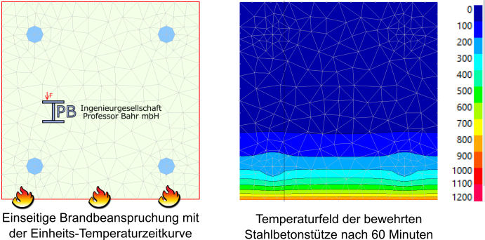
Regardless of whether you ultimately decide on a natural fire or an artificial fire curve, the result are time-dependent temperatures. The so-called thermal analysis makes use of this. To illustrate the principle of thermal analysis, let's imagine a reinforced concrete column that is integrated into a wall construction. To simplify matters, it is generally assumed in the fire design that the fire temperatures are identical in the entire fire area, i.e. there is no temperature gradient over the column height. Then it is enough to examine the column at the cross-sectional level (see the figure below). In addition, it should be taken into account that the column is integrated in the wall, i.e. the cross-section is only heated on one side (where the small flames can be seen in the illustration). In addition, we assume that the column has to achieve a fire resistance class R60 according to the building regulations and we therefore consider the ISO standard fire as fire curve.
The cross-section is divided (or: discretized) into elements using a special finite element program, which we can also imagine as fibers (right in the figure below). Now the time-dependent fire temperatures from step 2 are read in using the so-called time step method. Usual time steps are, for example, 10 seconds, i.e. our thermal analysis is carried out in (3600 seconds fire duration)/(10 seconds) = 360 time steps. Why this effort? This is due to the fact that the temperature in each fiber of the cross section changes with time. Linked to this, the temperature-dependent thermal material parameters (e.g. the thermal conductivity) must be recalculated for every fiber in each time step. As a result, the program saves the respective temperature in each fiber for each time step.

4th step: mechanical analysis
The program uses this data in the mechanical analysis. It also takes into account that the fibers tend to expand with increasing temperature (and vice versa). This means that stresses result from the fire exposure. In addition, the program takes of course into account that the reinforced concrete column has to resist mechanical loads from the structure. This means that it must be recorded that each individual fiber is less stable and less stiff at a higher temperature. If the program finds a balance between the load-bearing capacity of the fire-exposed column and the external loads over the entire duration of the fire, evidence of sufficient fire resistance is provided. Otherwise the column will fail after a certain fire duration and may have to be upgraded.
Sounds complicated and time-consuming? It is. Especially since it has not yet been mentioned that the reinforced concrete column is also deformed and that additional stresses can arise as a result of the so-called 2nd order theory. However, this would lead too far at this point. Nevertheless, there are simplified calculation methods in the Eurocodes, which were usually created on the basis of such computational simulations. However, the procedures often only apply if certain boundary conditions are met. For example, the methods do not take natural fires into account.
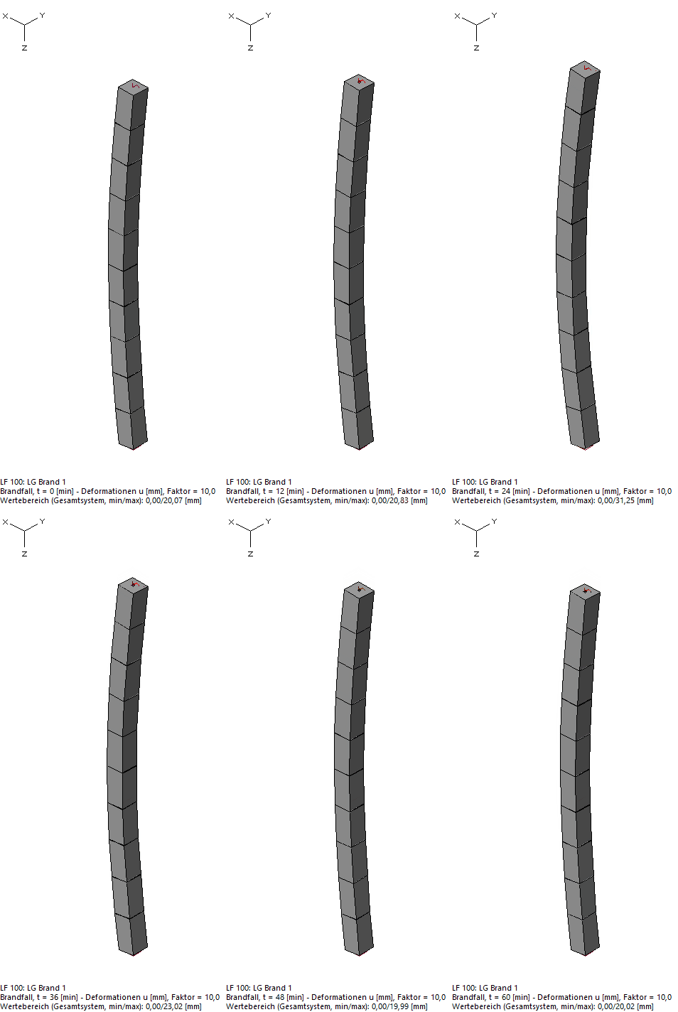
By the way, the reinforced concrete column we were considering would withstand the fire. In the animation below you can see the load-bearing behavior of the fire-loaded column.

5th step: Evaluation and interpretation of the results
Finally, it is also important to consider not only the load-bearing capacity, but also limit values for deformation. For example, the reinforced concrete column under consideration must not deform too much because otherwise adjacent components (such as a fire wall) could be damaged. Particular attention must also be paid to the connections between components.
And now?
As you can see, fire design is quite complex. As I am mainly active in this area, I am happy to provide you with active support in all of the steps described above. I look forward to hearing from you to classify your problem and to think together about whether a fire design is worthwhile. This advice is of course completely non-binding for you.